Creality 3D, a global leader in 3D printers, has introduced the 4.2.2 motherboard, an upgraded version of the popular 4.2.7 board.
This new motherboard features several advancements, including quieter operation, improved performance, and enhanced compatibility.
In this blog post, we will delve into the specifications of the Creality 4.2.2 board Specs and explore its key features.

Creality 4.2.2 Board Specs
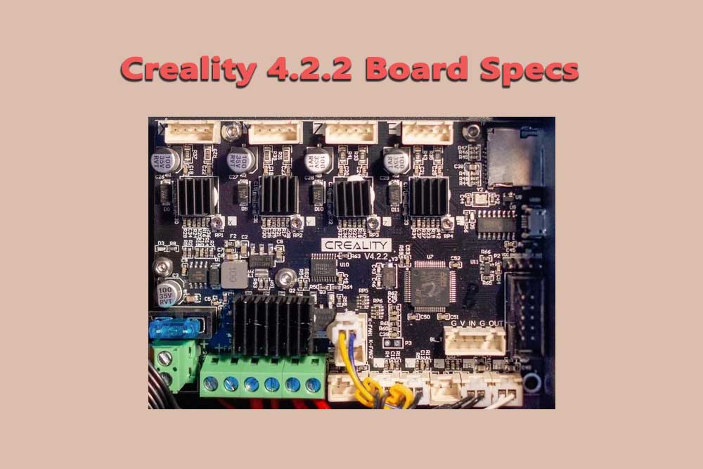
The Creality 4.2.2 motherboard is a 32-bit silent motherboard designed for Creality 3D printers. It features a powerful STM32F103RET6 Arm Cortex-M4 microcontroller with 256KB of flash memory and 128KB of SRAM. The motherboard also supports TMC2209 silent stepper motor drivers, which provide quieter operation and smoother motion.
Key specifications of the Creality 4.2.2 motherboard include:
- Microcontroller: STM32F103RET6 Arm Cortex-M4
- Flash memory: 256KB
- SRAM: 128KB
- Stepper motor drivers: TMC2209
- Input voltage: 24V
- Output voltage: 12V
- Dimensions: 110mm x 85mm x 15mm
- Weight: 132g
Key Features of the Creality 4.2.2 Motherboard
The Creality 4.2.2 motherboard offers several key features that enhance the performance and usability of Creality 3D printers:
-
Silent operation: The TMC2209 silent stepper motor drivers significantly reduce noise levels, making the printing process much quieter. This is particularly beneficial for users who print in home or office environments.
-
Improved performance: The powerful STM32F103RET6 Arm Cortex-M4 microcontroller provides faster processing and improved responsiveness, leading to more precise and consistent printing results.
-
Enhanced compatibility: The Creality 4.2.2 motherboard is compatible with a wide range of Creality 3D printers, including the Ender 3, Ender 5, and CR-10 series. This makes it a versatile option for users who own multiple printers.
-
Easy installation: The Creality 4.2.2 motherboard is designed for easy installation and can be swapped out with the older 4.2.7 motherboard without any modifications.
Benefits of Using the Creality 4.2.2 Motherboard
There are several benefits to using the Creality 4.2.2 motherboard:
-
Quieter printing: The TMC2209 silent stepper motor drivers reduce noise levels significantly, making printing more pleasant and less disruptive.
-
Improved print quality: The powerful microcontroller and stepper motor drivers provide faster processing and smoother motion, leading to more precise and consistent printing results.
-
Versatility: The Creality 4.2.2 motherboard is compatible with a wide range of Creality 3D printers, making it a suitable choice for users with multiple printers.
-
Easy upgrade: The motherboard is easy to install and can be swapped out with the older 4.2.7 motherboard without any modifications.
Creality 4.2.2 board parts:
The board has a power supply connector, 4 fan headers, and a microSD card slot. The power supply provides 12V/24V power options. The heated bed has an integrated Mosfet for safety.
The board uses an MKS Gen L mainboard with a TMC2130 stepper driver. 2 of the 4 fan headers are used for part cooling fans.
The other 2 can be used for controlling custom fans.
There is also a USB port on the board so you can connect it to your computer to print directly from your computer without the need of an external controller.”
Power Supply of Creality 4.2.2:
“The power supply provides 12V/24V power options with an ATX power connector. The heated bed has a Mosfet integrated for safety, and the power supply for it is also included.
There are 4 fan headers, with 2 being used for part cooling fans and the other 2 can be used for controlling your own custom fans. Overall, the Creality 4.2.2 is a great option for those looking for a quality controlled board with lots of features.”
USB Port of Creality 4.2.2:
The USB port on the board allows you to connect it to your computer to print directly from your computer without the need of an external controller. The USB port is located on the side of the board near the power supply connector.
4-pin Connector of Creality 4.2.2:
The 4-pin connector is used to connect the heated bed to the power supply. The connector is located on the side of the board near the power supply connector. The heated bed has a Mosfet integrated for safety, and the power supply for it is also included.
MicroSD Card Slot of Creality 4.2.2:
The microSD card slot is located on the side of the board near the USB port. The microSD card slot allows you to print directly from your computer without the need of an external controller. The microSD card slot is compatible with SD cards up to 32GB.
3D Printer Connector of Creality 4.2.2:
The 3D printer connector is located on the back of the board near the power supply connector. The 3D printer connector is used to connect the board to your 3D printer. The 3D printer connector is a JST-XH 2.54mm pitch connector.
MKS Gen L Mainboard:
The MKS Gen L mainboard is a great option for those looking for a quality controlled board with lots of features. The board provides 12V/24V power supply options with an ATX power connector.
It uses an MKS Gen L mainboard with a TMC2130 stepper driver. The heated bed has a Mosfet integrated for safety, and the power supply for it is also included. There are 4 fan headers, with 2 being used for part cooling fans and the other 2 can be used for controlling your own custom fans.
The board also includes a microSD card slot so you can print directly from your computer without the need of an external controller.
TMC2130 Stepper Driver:
“The TMC2130 stepper driver is a great option for those looking for a quality controlled board with lots of features. The TMC2130 stepper driver provides 12V/24V power supply options with an ATX power connector.
It uses an MKS Gen L mainboard with a TMC2130 stepper driver. The heated bed has a Mosfet integrated for safety, and the power supply for it is also included.
There are 4 fan headers, with 2 being used for part cooling fans and the other 2 can be used for controlling your own custom fans.
Heated Bed:
“The heated bed has a Mosfet integrated for safety, and the power supply for it is also included. The heated bed uses an MKS Gen L mainboard with a TMC2130 stepper driver. There are 4 fan headers, with 2 being used for part cooling fans and the other 2 can be used for controlling your own custom fans.
Fan Headers:
“The fan headers are used to connect the fans to the power supply. The fan headers are located on the side of the board near the power supply connector. There are 4 fan headers, with 2 being used for part cooling fans and the other 2 can be used for controlling your own custom fans.
Part Cooling Fans:
“The part cooling fans are used to cool the parts of your 3D printer. The part cooling fans are located on the side of the board near the power supply connector. There are 4 fan headers, with 2 being used for part cooling fans and the other 2 can be used for controlling your own custom fans.”
The Creality 4.2.2 motherboard is a significant upgrade over the previous 4.2.7 motherboard, offering a quieter operation, improved performance, and enhanced compatibility. With its numerous benefits, the Creality 4.2.2 motherboard is a valuable addition to any Creality 3D printer.
FAQ’s:
Q: Is the microSD card slot compatible with SD cards up to 32GB?
A: Yes, the microSD card slot is compatible with SD cards up to 32GB.
Q: Where is the 3D printer connector located?
A: The 3D printer connector is located on the back of the board near the power supply connector.
Q: Can I use the fan headers to control my own custom fans?
A: Yes, you can use the fan headers to control your own custom fans.
Q: What is the purpose of the part cooling fans?
A: The part cooling fans are used to cool the parts of your 3D printer.

