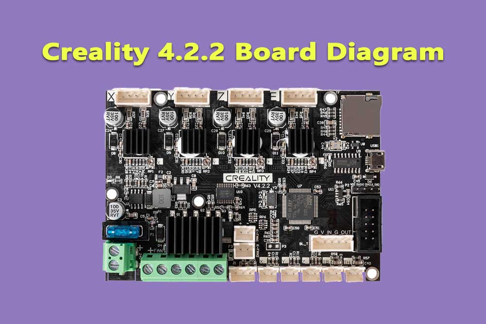
If you’re diving into the world of 3D printing, the Creality 4.2.2 board is a game-changer that deserves your attention. Renowned for its robust performance and versatility, this control board is integral to enhancing your printing experience.
In this post, we’ll provide a comprehensive overview of the Creality 4.2.2 board diagram, its specifications, and key features that set it apart from the competition. Whether you’re a seasoned pro or a beginner looking to upgrade, understanding this powerful board will help you unlock its full potential and achieve stunning print results.
Let’s explore what makes the Creality 4.2.2 an essential component in modern 3D printing setups!
How to create board diagram?
Board diagrams can be created using a variety of software programs, such as Microsoft Visio, Eagle, or KiCAD. The exact process for creating a board diagram will vary depending on the program that is used.
However, typically the first step is to create a schematic drawing of the circuit. This involves drawing the individual components of the circuit, and connecting them together with wires.
Once the schematic is complete, the board diagram can be generated by adding the component footprints and routing the wires between them.
Board diagram electronics:
Board diagrams are also used in the electronics industry to create circuit boards. In this application, the board diagram is used as a blueprint for the circuit board. It shows the locations of the components, and how they are interconnected.
The board diagram is then used to create the layout of the circuit board, which is used to manufacture the final product.
Board Diagram Software:
There are many software programs that can be used to create board diagrams. Some of the more popular ones include Microsoft Visio, Eagle, and KiCAD. These programs allow you to create schematic drawings of electrical circuits, and then generate board diagrams from them.
The process for creating a board diagram will vary depending on the program that is used, but typically it involves drawing the individual components of the circuit, and connecting them together with wires. You can also add component footprints and routing information to create a complete board diagram.
Creality 4.2.2 Board Specs
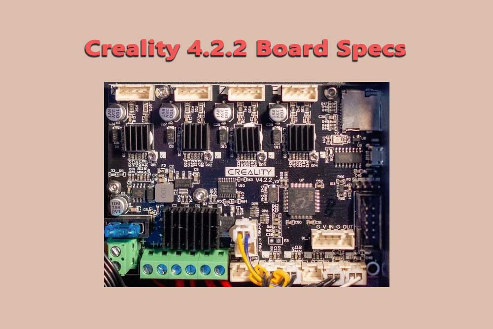
The Creality 4.2.2 motherboard is a 32-bit silent motherboard designed for Creality 3D printers. It features a powerful STM32F103RET6 Arm Cortex-M4 microcontroller with 256KB of flash memory and 128KB of SRAM. The motherboard also supports TMC2209 silent stepper motor drivers, which provide quieter operation and smoother motion.
Key specifications of the Creality 4.2.2 motherboard include:
- Microcontroller: STM32F103RET6 Arm Cortex-M4
- Flash memory: 256KB
- SRAM: 128KB
- Stepper motor drivers: TMC2209
- Input voltage: 24V
- Output voltage: 12V
- Dimensions: 110mm x 85mm x 15mm
- Weight: 132g
Key Features of the Creality 4.2.2 Motherboard
The Creality 4.2.2 motherboard offers several key features that enhance the performance and usability of Creality 3D printers:
-
Silent operation: The TMC2209 silent stepper motor drivers significantly reduce noise levels, making the printing process much quieter. This is particularly beneficial for users who print in home or office environments.
-
Improved performance: The powerful STM32F103RET6 Arm Cortex-M4 microcontroller provides faster processing and improved responsiveness, leading to more precise and consistent printing results.
-
Enhanced compatibility: The Creality 4.2.2 motherboard is compatible with a wide range of Creality 3D printers, including the Ender 3, Ender 5, and CR-10 series. This makes it a versatile option for users who own multiple printers.
-
Easy installation: The Creality 4.2.2 motherboard is designed for easy installation and can be swapped out with the older 4.2.7 motherboard without any modifications.
Benefits of Using the Creality 4.2.2 Motherboard
There are several benefits to using the Creality 4.2.2 motherboard:
-
Quieter printing: The TMC2209 silent stepper motor drivers reduce noise levels significantly, making printing more pleasant and less disruptive.
-
Improved print quality: The powerful microcontroller and stepper motor drivers provide faster processing and smoother motion, leading to more precise and consistent printing results.
-
Versatility: The Creality 4.2.2 motherboard is compatible with a wide range of Creality 3D printers, making it a suitable choice for users with multiple printers.
-
Easy upgrade: The motherboard is easy to install and can be swapped out with the older 4.2.7 motherboard without any modifications.
How to install board diagram?
Board diagrams can be used to troubleshoot and repair electrical circuits, and to design new circuits. They can be very simple, or very complex. Board diagrams play an important role in the design and troubleshooting of electrical circuits.
They allow engineers to see how the components in a circuit are interconnected, and how they interact with each other. Board diagrams can help identify problems with a circuit, and help find the cause of failures.
They can also be used to verify the operation of a circuit, and to study its behavior.Board diagrams can be created using a variety of software programs, such as Microsoft Visio, Eagle, or KiCAD. The exact process for creating a board diagram will vary depending on the program that is used.
Common problems of board diagram:
Incorrect component placement: If the components in a circuit are not placed correctly, it can cause problems with the circuit.
Improper wiring: Improperly wired circuits can be difficult to troubleshoot and may not work properly.
Incorrect or missing footprints: Incorrect or missing footprints can cause errors when routing the wires between the components.
Unrouted wires: Unrouted wires can cause short circuits and other problems.
Board diagrams are an important tool for designing and troubleshooting electrical circuits. They allow engineers to see how the components in a circuit are interconnected, and how they interact with each other. Board diagrams can help identify problems with a circuit, and help find the cause of failures.
How to remove these problems?
There are a number of ways to correct problems with a board diagram.
- Incorrect component placement: If the components in a circuit are not placed correctly, it can be corrected by moving the components to the correct location.
- Improper wiring: Improperly wired circuits can be corrected by rewiring the circuit.
- Incorrect or missing footprints: Incorrect or missing footprints can be corrected by adding the appropriate footprint to the diagram.
- Unrouted wires: Unrouted wires can be corrected by routing the wires between the components.
Board diagrams are an important tool for designing and troubleshooting electrical circuits. They allow engineers to see how the components in a circuit are interconnected, and how they interact with each other.
Board diagrams can help identify problems with a circuit, and help find the cause of failures. By correcting the common problems with board diagrams, engineers can create accurate and reliable circuit diagrams.
Board diagrams can help identify problems with a circuit, and help find the cause of failures. By correcting the common problems with board diagrams, engineers can create accurate and reliable circuit diagrams.
FAQ’s:
What is a board diagram?
A board diagram is a schematic diagram of an electrical circuit. It shows the components of the circuit, and how they are interconnected.
What is the purpose of a board diagram?
Board diagrams are used to design and troubleshoot electrical circuits. They allow engineers to see how the components in a circuit are interconnected, and how they interact with each other. Board diagrams can help identify problems with a circuit, and help find the cause of failures.
How do I create a board diagram?
Board diagrams can be created using a variety of software programs, such as Microsoft Visio, Eagle, or KiCAD. The exact process for creating a board diagram will vary depending on the program that is used.
What are the common problems with board diagrams?
Board diagrams can have a number of common problems, such as incorrect component placement, improper wiring, incorrect or missing footprints, and unrouted wires.
How can I correct these problems?
There are a number of ways to correct problems with a board diagram. This includes moving components to the correct location, rewiring the circuit, adding footprints to the diagram, and routing the wires between components.
Hassan Khan
Hassan Khan is a leading voice when it comes to the innovative world of additive manufacturing. A mechanical engineer by training, Hassan quickly recognized the transformative potential of 3D printing, diving headfirst into the intricacies of printer design, filament research, and software optimization. At CrealityLovers.com, Hassan shares his profound knowledge, from insightful reviews and tutorials to forward-thinking op-eds that forecast the future of 3D printing. Hassan's commitment goes beyond the written word. Hassan Khan aims to empower every reader, from novices to industry experts, ensuring they make informed decisions in their 3D printing endeavors.